10 Best Pneumatic Conveying Blower Manufacturers
Choosing a Pneumatic Conveying Blower is not just a matter of comparing horsepower. Material properties, conveying distance, pressure, airflow, and duty cycle all affect performance. A fine powder moving through a long pipeline creates different demands from coarse pellets travelling a short route. Small details matter.
The U.S. Department of Energy’s Improving Compressed Air System Performance: A Sourcebook for Industry reports that compressed-air systems account for roughly 10% of electricity used in U.S. industry. That figure covers many applications, not pneumatic conveying alone. Still, it shows why efficiency deserves close attention. A blower that is oversized or poorly matched can waste energy, while an undersized unit may struggle to maintain stable flow.
David Mills, author of Pneumatic Conveying Design Guide, is a recognized specialist in conveying-system design. A fair paraphrase of his guidance is simple: match the system to the material and operating duty, rather than choosing equipment in isolation. That principle helps frame this list of 10 manufacturers. The comparison should consider technical support, product range, operating efficiency, and suitability for the actual process—not marketing claims alone. Manufacturer specifications are useful, but they cannot replace application-specific engineering. And even a careful shortlist has limits: plant layout, material behavior, and maintenance needs can change the right choice.
Pneumatic Conveying Basics: Typical Dilute-Phase Velocities of 15–30 m/s
In dilute-phase pneumatic conveying, moving air keeps particles suspended inside a pipeline. Typical conveying velocities are often around 15–30 m/s, but this range is a guide, not a universal setting. Fine powders may travel differently from coarse granules. Material shape, moisture, pipe diameter, and solids loading all affect the required airflow.
Too little velocity can let particles settle, especially at bends or horizontal runs. Too much can increase wear, particle breakage, and energy use. A technician might check pressure readings, listen for changes in the line, and inspect elbows for buildup. Small clues matter. A pale dust trail near a joint may signal leakage, while a sudden pressure rise can suggest a developing blockage.
Selecting a conveying blower means matching airflow and pressure to the actual system, not choosing from velocity alone. Start with the material supplier’s data and the pipeline layout, then confirm performance during controlled operation. I would treat calculated values as estimates; real installations can behave stubbornly. Adjustments should be measured, documented, and checked against product condition and line stability.

Typical Dilute-Phase Conveying Velocity
A reference range for dilute-phase pneumatic conveying, shown in meters per second.
Typical dilute-phase conveying velocities are approximately 15–30 m/s. The suitable operating velocity depends on material properties, pipe layout, and system design; use material-specific testing and engineering guidance when selecting a setpoint.
Blower Types: Roots, Screw, and Centrifugal Designs for Conveying Systems
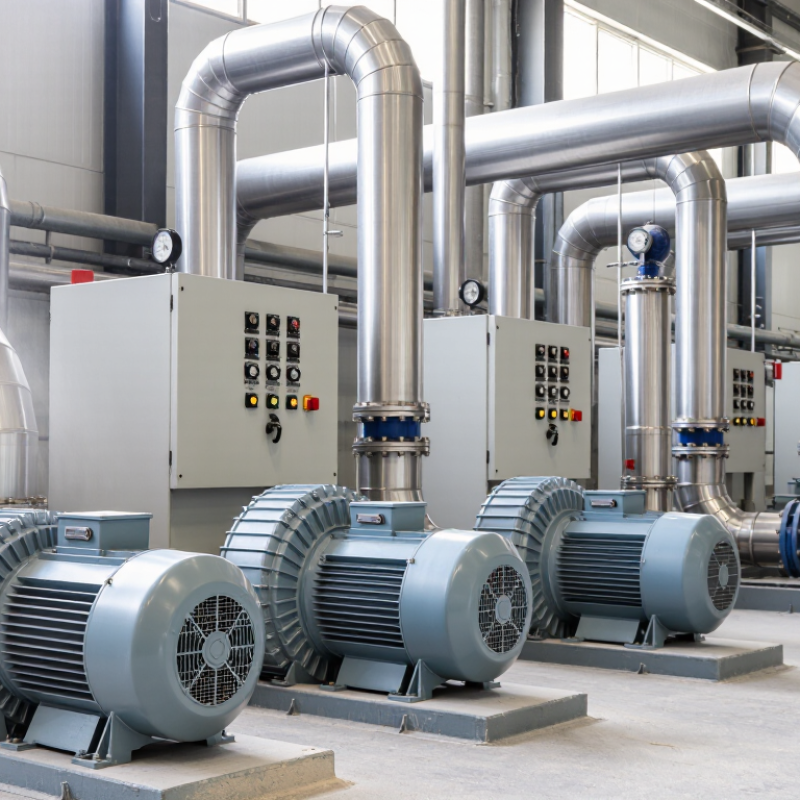
Pneumatic conveying performance depends on more than blower horsepower. Material size, moisture, route length, and pickup points shape the required airflow and pressure. Roots blowers move a near-fixed volume of air with each rotation. They suit many steady, low-to-medium-pressure lines, but discharge air can become hot. A cooler, relief valve, or sound enclosure may be needed. Watch the fines.
Screw blowers use paired rotors and internal compression, often delivering air efficiently across stable operating conditions. Their initial cost and service needs can be higher, and dusty intake air may shorten rotor life. Keep filtration disciplined.
Centrifugal blowers add velocity through an impeller, then convert it into pressure. They can serve high-volume systems, especially where conveying pressure is modest and demand stays predictable. At low flow, performance may fall quickly unless controls match the operating range.
The practical choice begins with the conveying curve, not a catalog headline. Compare required airflow at actual pressure, including pipe bends, filters, and receiver losses. Fragile pellets may need gentler velocities; abrasive powder can demand tougher bends and careful wear checks. That trade-off is easy to underestimate.
A measured commissioning run can reveal plugging, heat, and energy use before routine operation. Allow for uncertainty: feed consistency changes, and yesterday’s settings may not fit tomorrow’s batch.
Key Performance Data: Airflow, Pressure, Power, and ISO 1217 Testing
When comparing pneumatic conveying blower manufacturers, read airflow and pressure as a matched operating point, not separate headline numbers. A unit rated for 1,000 m³/h at 60 kPa may deliver less flow after filters, pipe bends, and material pickup add resistance. Ask whether published airflow is stated at inlet conditions, and whether pressure means gauge or absolute pressure. Small differences matter.
Power figures deserve the same scrutiny. At 1,000 m³/h and 60 kPa, ideal air power is about 16.7 kW; at 65% overall efficiency, estimated input rises to roughly 25.6 kW. This is a calculation, not a guaranteed field result. The U.S. Department of Energy’s Improving Compressed Air System Performance sourcebook notes that compressed air can account for around 10% of industrial electricity use, though actual shares vary by facility. A few kilowatts can therefore matter over long shifts.
ISO 1217:2009, Displacement compressors—Acceptance tests, provides standardized methods for testing displacement-compressor capacity and power. Check whether a blower’s reported results were measured under comparable inlet temperature, pressure, and test conditions; the standard is not a substitute for application-specific conveying trials. Request the test sheet, including measured airflow, discharge pressure, shaft or input power, and stated tolerances. A neat datasheet can still hide assumptions. Ask for operating data at the duty point you actually need.
How to Select a Blower: Material, Conveying Phase, and System Pressure Loss
Start with the material, not the blower catalogue. Particle size, bulk density, moisture, and fragility affect both conveying behavior and equipment wear. Fine powders may disperse readily, while damp or irregular particles can settle or bridge. David Mills’s Pneumatic Conveying Design Guide describes dilute-phase conveying velocities commonly around 15–30 m/s; dense-phase systems operate more slowly, often around 2–8 m/s. These are design ranges, not guarantees. Test the actual material where possible.
Choose the conveying phase to suit the product and route. Dilute phase can work well for steady, longer-distance transport, but higher air velocity may increase particle impact at bends. Dense phase can reduce velocity and product damage, yet requires careful control of solids feeding and pressure. Real plants are rarely that tidy. A small change in moisture or feed rate can alter performance, so leave room for operating variation.
Estimate total pressure loss across the entire system, including straight pipe, elbows, pickup points, filters, and discharge equipment. The U.S. Department of Energy’s Improving Fan System Performance guide emphasizes evaluating fans against the system curve; the same operating-point principle matters when matching a blower. Do not size from pipe length alone. Record the required flow and pressure at the blower inlet, account for air temperature and altitude, then check the operating point with the system supplier. I would still verify the estimate against measured pressure after commissioning.
10 Leading Manufacturers Compared by Applications, Capacity, and Service Support
The ten leading pneumatic conveying blower manufacturers differ less by headline claims than by how well their equipment fits a process. Dense-phase systems may need steady pressure at lower airflow, while dilute-phase lines often require higher volume and careful velocity control. A cement transfer line, for example, faces different wear and dust challenges from a food ingredient system. Fit matters.
Compare capacity using airflow and pressure at the actual duty point, not the largest number on a brochure. Ask for performance curves, motor data, noise figures, and startup guidance. Some suppliers offer Roots, screw, or centrifugal designs, each with trade-offs in efficiency, footprint, and maintenance. Quiet running helps. It is not the whole story.
Service support can distinguish otherwise similar options. Check commissioning availability, spare-parts lead times, troubleshooting access, and whether technicians understand conveying systems, not only blowers. Request references from applications using comparable materials and line lengths. A polished proposal is useful, but it cannot replace operating evidence. I would question any comparison that treats capacity as fixed; temperature, altitude, filters, and pressure losses can change real output. Even a strong shortlist may need a site review before purchase.
| Anonymous Profile | Typical Blower Technology | Best-Fit Applications | Indicative Airflow Capacity | Typical Differential Pressure | Service Support to Confirm |
|---|---|---|---|---|---|
| Profile 1 Positive displacement | Rotary-lobe blower, fixed-speed package | Dilute-phase conveying of grain, flour, pellets, and other dry bulk materials | About 100–10,000 m³/h | About 0.3–1.0 bar | Check local parts stock, overhaul capability, and commissioning availability. |
| Profile 2 Positive displacement | Rotary-lobe blower with variable-frequency drive | Systems requiring adjustable airflow, such as multi-line conveying or changing production rates | About 100–10,000 m³/h | About 0.3–1.0 bar | Confirm drive commissioning, controls integration, and service response coverage. |
| Profile 3 Oil-free option | Oil-free screw blower | Applications where oil-free conveying air is specified, including food and pharmaceutical processes | About 100–12,000 m³/h | About 0.5–1.2 bar | Verify air-quality documentation, element service intervals, and access to trained technicians. |
| Profile 4 High-volume | Multistage centrifugal blower | High-flow dilute-phase conveying and central air systems serving several users | About 1,000–100,000 m³/h | About 0.2–1.0 bar | Ask about balancing, vibration diagnostics, and planned maintenance support. |
| Profile 5 High-speed | High-speed turbo blower | Variable-flow conveying systems where compact equipment and efficient operation are priorities | About 500–30,000 m³/h | About 0.3–1.0 bar | Confirm specialist electronics support, spare-part lead times, and remote diagnostics options. |
| Profile 6 Compact systems | Side-channel (regenerative) blower | Small-scale conveying, light-duty material transfer, and low-capacity applications | About 20–1,500 m³/h | About 0.1–0.5 bar | Check suitability for the required duty cycle and availability of replacement bearings and seals. |
| Profile 7 Vacuum conveying | Rotary-lobe vacuum blower | Vacuum conveying systems and suction-side material transfer | About 100–10,000 m³/h | Vacuum capability depends on the package and operating point; confirm the system curve. | Verify vacuum-side filtration support, seal service, and package-specific troubleshooting. |
| Profile 8 Low-flow option | Dry claw vacuum pump or blower | Clean, dry vacuum conveying in applications with modest airflow requirements | About 50–4,000 m³/h | Depends on configuration; confirm the permitted pressure and vacuum operating range. | Ask about claw inspection, service intervals, and the availability of trained local support. |
| Profile 9 Wet-service option | Liquid-ring vacuum pump | Vacuum conveying where the process gas may be humid or contain condensable vapour | About 50–10,000 m³/h | Depends on seal-liquid temperature and configuration; confirm the operating point. | Confirm seal-liquid management support, materials compatibility guidance, and service access. |
| Profile 10 Packaged systems | Engineered blower package combining blower, motor, silencer, filter, and controls | Turnkey installations requiring coordinated equipment, instrumentation, and system integration | Package-dependent; commonly selected within the ranges of the underlying blower technology | Package- and duty-dependent; size against the conveying system pressure drop | Clarify responsibility for commissioning, controls, warranty coordination, and emergency callouts. |
Comparison note: No company or brand names are shown. These rows describe common blower technology and package profiles, not verified specifications for individual manufacturers. Airflow and pressure ranges are indicative only; actual operating limits depend on the model, gas conditions, altitude, and system design. Confirm performance at the required duty point with the supplier.
